- Research
- Open access
- Published:
Compressive sensing imaging for general synthetic aperture radar echo model based on Maxwell’s equations
EURASIP Journal on Advances in Signal Processing volume 2014, Article number: 153 (2014)
Abstract
A general echo model is derived for the synthetic aperture radar (SAR) imaging with high resolution based on the scalar form of Maxwell’s equations. After analyzing the relationship between the general echo model in frequency domain and the existing model in time domain, a compressive sensing (CS) matrix is constructed from random partial Fourier matrices for processing the range CS SAR imaging. Simulations validate the orthogonality of the proposed CS matrix and the feasibility of CS SAR imaging based on the general echo model.
1 Introduction
Synthetic aperture radar (SAR) has been in development for more than 60 years. Many operations, including strip-map, spotlight, scan, and multiple platform-borne SAR systems have become more and more popular in recent years. SAR systems have been used in many fields, such as soil moisture, forestry, wetland, and agriculture. Due to the higher resolution of SAR image required, the accuracies of the echo models and imaging algorithms need improvement. Because the echo model is a kind of output, it forms a theoretical basis for all SAR imaging algorithms. From an engineering point of view, the traditional echo model is the time-delayed signal of the transmitted signal. There are lots of approximations for echo model. Let us recall the echo signal model. The SAR echo is one of electromagnetic wave forms, and Maxwell’s equations are the basic and accurate tools for electromagnetic wave measurement. Mathematically, the SAR imaging procedure is an inverse problem of the electromagnetic wave. Many mathematical and practical researchers are interested in these types of inverse problems [1–5].
In recent studies of SAR and inverse synthetic aperture radar (ISAR), the data size trends larger and larger as the need for high resolution images becomes greater and greater. It costs too much and many times, the data cannot be downloaded in real time from some space-borne platforms, such as satellites. How to disperse the data size efficiently and decrease the data ratio is a real problem for engineers. The good news is that compressive sensing (CS) theory addresses at least some of these problems [6]. Random sampling theory, the CS sampling, and construction proposed by Donoho et al. in 2006 [7–9] and Baraniuk in 2007 [10] may also help in this endeavor. Many publications in the literature cast the CS into radar imaging [11–16], where they analyzed the sparse characteristics of SAR signals in different domains. Those are the fundamentals of reconstructing the scenes from the equivalent down-sampling data set. Another application of the CS SAR imaging is to construct the CS matrix and its optimization [17]. However, most of the past research works are focused on the classical echo model for SAR [18] and ISAR image [19].
In this paper, our goal is to analyze a general echo model and construct a new CS matrix for the SAR imaging. We use the partial differential Maxwell’s equations to derive the electronic field and then obtain the general echo model in frequency domain and time domain. Based on this general model, considering the sparse characteristic of the scene, we will construct the corresponding orthogonal CS matrix for the SAR imaging.
Our paper is organized as follows. Section 2 derives the general SAR echo model based on Maxwell’s equations. In Section 3, a new CS matrix is constructed for the CS imaging based on the above general echo model in frequency domain. In Section 4, simulations are given to validate the orthogonality of the CS matrix and the imaging performance. Some comparisons of two CS methods and the evaluation method with indices are also provided. Section 5 concludes the paper.
2 General SAR echo model
From the scalar form of Maxwell’s equations, the incident and scattering fields are analyzed first, and then the general SAR echo model [20] is derived according to the antenna theory.
2.1 Maxwell’s equations and field expressions
In this paper, the simplified scalar form of Maxwell’s equations is used directly instead of the vector form of Maxwell’s equations [21]. That is,
where x is the three-dimensional position vector, c(x) is the local propagation speed of electromagnetic waves and c(x) = c0 in free space (usually, c0 is the speed of light), εtot(t,x) and j(t,x) is the total scalar field and the current density on the antenna, respectively. c(x) satisfies , where V(x) stands for the target reflectivity function, which will be reconstructed from radar echoes. εtot(t,x) = εin(t,x) + εsc(t,x), where εin(t,x) and εsc(t,x) are the incident scalar field and the scattered scalar field, respectively. And εin(t,x) satisfies
Then, the expressions of scattered field and the incident field are as follows:
where , called Green’s function [22], is the fundamental solution of the partial differential equation .
Considering the single scattering approximation in Equation 3, the scattered field is reduced to
For simplicity, the following analysis is complemented in frequency domain ω instead of time domain t.
where Esc(ω,x) and Ein(ω,x) are the Fourier transforms of εin(t,x) and εin(t,x), respectively; is the frequency expression of Green’s function g(t,x); is the wavenumber in range direction; and J(ω,x) is the current source in the frequency domain. Then, the scattered field with a theoretical point antenna is
2.2 Mathematical signal model
2.2.1 Radiation pattern for a SAR antenna
Generally, the transmitting and receiving antenna is composed with many cells. For the sake of simplicity, a planar radar antenna over an aperture [-a,a]×[-b,b] is analyzed and the current density I is constant; then, the radiation scalar F(k,x) can be expressed by
where , is corresponding to the antenna direction.
Let p(t) be the transmitted signal; then, the current density on antenna j(t,x) is proportional to p(t) and independent of position. So, J(ω,x) is proportional to the spectrum of transmitted signal P(ω). Then,
where is just an amplitude function independent of the transmitted signal, with a function of wavenumber k, which varies for a wideband signal even within a short pulse time duration. In fact, this corresponds to the frequency characteristics of antenna, especially under wide bandwidth.
2.2.2 Mathematical model of received echo
Suppose that the center of antenna is located at x0, the incident field Ein(ω,x) and scattered field are
When a monostatic SAR receives echoes, the stop-go approximation is applied and therefore the received echo is expressed by
where W(ω,y) is the weight function of the antenna cell at the position y. Substitute Equation 12 into Equation 13, we have
Considering the far field condition, and |y-z|-1≈|z-x0|-1 are adopted to produce the following form
Putting the unit weight function W(ω,y) = 1 yields
Until now, we get the general echo model in frequency domain. According to the properties of Fourier transform, the general echo model in time domain can be expressed by
where is the second derivative of p(t), is the inverse Fourier transform of , and ⊗ is convolution on t. If we neglect the antenna’s variety with frequency ω or wavenumber k, that’s , where is the wavenumber corresponding to the carrier frequency, the above expression can be simplified by
Even if some approximation about antenna radiation has been made, we can also find the difference between the above model and the transitional echo model, which is as simple as the summing the delayed signal of the transmitted signal. That is, the general echo is not the direct delay of the transmitted signal but the second order differential function of the transmitted signal. However, because Doppler phase is much more important in SAR imaging than the complex amplitude, the amplitude modulation is not serious for traditional SAR systems. In [20], the relation and difference between the general echo model and the classical model were minutely analyzed. However, for some high resolution applications, the differences may not be ignored. In this paper, to avoid error as much as possible, we try to find a CS matrix for the general echo model in frequency domain directly.
3 Compressive sensing imaging for SAR
3.1 Basics of compressive sensing
Because of the potential advantages for SAR imaging, there has been a wealth of research work directed towards CS since 2006. The spirit of CS is the sparse presentation under some basis. Suppose Ψ∈CN × N (in fact, the matrix was defined on RN × N originally and could be expanded to the complex matrix) is the orthogonal basis matrix and s∈RN is the coefficients vector, the signal x∈RN can be expressed by
where the transform coefficient s can be calculated by s = Ψ-1x mathematically. If there are only K(≪N) non-zero values (or small absolution) in s, the signal x is sparse in the corresponding domain and can be reconstructed by a few random samples with very high probability. Suppose the linear observing process is Φ∈RM × N, where M<N, the observation data y∈RM is
where the observing matrix Θ = Φ Ψ∈CM × N. Based on CS theory, the reconstruction of the sparse coefficient s can be resolved by the following optimization problem.
Because l0 normalization optimization problem is difficult to resolve, l0 normalization is replaced by l1 normalization for the actual solution. Then, the signal x is to be estimated by .
3.2 Compressive sensing matrix for SAR imaging
To apply CS to SAR imaging, we should consider two conditions: the sparsity of signal and the CS matrix. For the first condition, according to the theory of electromagnetic scattering, some targets can be thought as combinations of several strong scatterers; even for some continuous distributed scenes, the sparse coefficients can be found in the frequency domain or wavelet domain, etc. So, the sparsity of echo signal has been discussed for some special applications, such as ocean remote sensing. For the other condition, the previous literature [23, 24] presented one kind of sensing matrices in time domain as follows.
where is the transmitted linear frequency modulation (LFM) chirp signal, b is the frequency modulation ratio of the chirp signal, f s is the sampling frequency, and τ and N τ = τ f s are the pulse width and point numbers of the chirp signal, respectively.
This CS matrix is based on the idea that the echo signal is the delay of the transmitted signal, and its orthogonality also was validated. However, according to Section 2 of this paper, we have found that the general echo model is the expansion of the simple delay model of the transmitted signal, and it is more accurate for some high resolution applications. Our goal is to find a CS matrix corresponding to the general echo model directly.
In the beginning, the received signal after discrete processing from the frequency domain expression (Equation 16) can be expressed as
where the subscript m represents the frequency number for fast time of echo, n represents the target index, N p is the number of the discrete targets, R n is the range between the n th target point located at z n and the center of the antenna located at x0, ω m = 2π f s (m/N-1/2) is the discrete frequency, m = 0,1,…,N-1, and N is the number of Fourier transform. Suppose the scatter coefficients vector , the (m,n)-th element of the CS matrix Ψ can be constructed as
With these definitions, it is not hard to validate D rec (x0) = Ψ Σ. Because we use the general echo model in frequency domain, the CS matrix Ψ is also the function of the general transmitted signal in frequency domain P(ω m ). For instance, if the transmitted signal is a chirp signal, according to the principle of stationary phase, we can get , where A is a complex constant, and then the CS matrix Ψ becomes
To validate the orthogonality of the CS matrix for different rows, the following correlation will be calculated
It is not hard to find that because of the cophasal stacking effect. And after normalization for each row, the correlation matrix is approximately an identical matrix. The orthogonality will be validated in the next section. On the other hand, besides Gaussian and Bernoulli matrices, another very important class of structured random matrices is the random partial Fourier matrix, which is also the object of study in the very first paper on CS [9]. In fact, a random partial Fourier matrix relates the time domain signal and the sparse spectrum items; also, it is the first time to construct an orthonormal basis in CN × N rather than RN × N. It has been proved that the Fourier matrix satisfied the restricted isometry property (RIP) and can be applied to CS reconstruction. The proposed matrix defined by Equations 24 or 25 can be thought as one form of the Fourier matrix and can be applied for CS imaging for the general SAR echo model. Randomly selected M rows from Ψ will generate a random partial Fourier matrix Θ; the range signal reconstruction from the SAR echoes can be accomplished in range frequency domain instead of the traditional match filtering.
In this paper, the orthogonal match pursuit (OMP) algorithm [25] is unitized for the reconstruction of the sparse signal, which corresponds to the discrete scattering coefficients in SAR imaging. The orthogonality of the CS matrix makes sure of the maximum probability of reconstruction quickly.
4 Simulations
In this section, the properties of the CS matrix Ψ are analyzed first, then the CS imaging for a point scene is simulated with both the previous time-domain CS matrix like Equation 22 and the proposed matrix corresponding to the general echo model defined by Equation 24. The comparison of the range reconstruction results after CS and the final imaging results are given.
4.1 Simulation parameters
The main parameters for the below simulations are listed in Table 1. To compare with the time-domain CS method, the most common chirp signal is chosen as the transmitted signal. In order to display the affections of wide bandwidth, the frequency of chirp signal ranges from 800 to 1,200 MHz, and the ratio of bandwidth and carrier frequency is up to 40%.
4.2 Results and discussion
4.2.1 Compressive sensing matrix properties
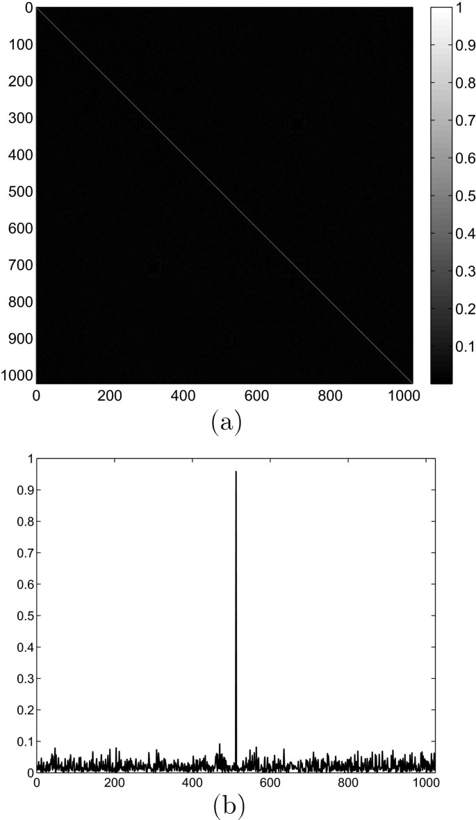
Since there is some complex magnitude term in Equation 25, the accurate proof of the orthogonality based on Equation 26 is difficult. However, Figure 1 illustrates the correlation matrix of Ψ by numerical simulation.
According to Figure 1, the diagonal elements of the correlation matrix trend to 1, and others are very small. This correlation matrix is approximate to the identical matrix, so the CS matrix Ψ can be thought as orthogonal matrix.
4.2.2 Imaging results and evaluation
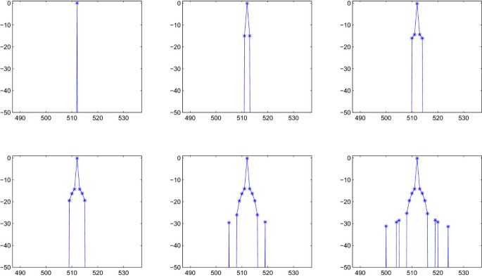
Before analyzing the simulation results, we discuss the evaluation method first. Fourier interpolation is often applied into the evaluation of the traditional range compressed result or SAR image. However, in the previous CS reconstruction, it is acceptable that the range reconstruction result has no sidelobe [18, 26, 27], and Fourier interpolation is not suitable to evaluate the result. This phenomenon might be explained that when K is 1 or a very small number, after reconstruction of compressive sensing, there is at most only 1 non-zero value in each range profile, like a delta function, and any interpolation does not fit during evaluation. According to our simulation during range CS reconstruction, we still set different sparse coefficients K for a single target, and a bigger K will expose the more sidelobes.
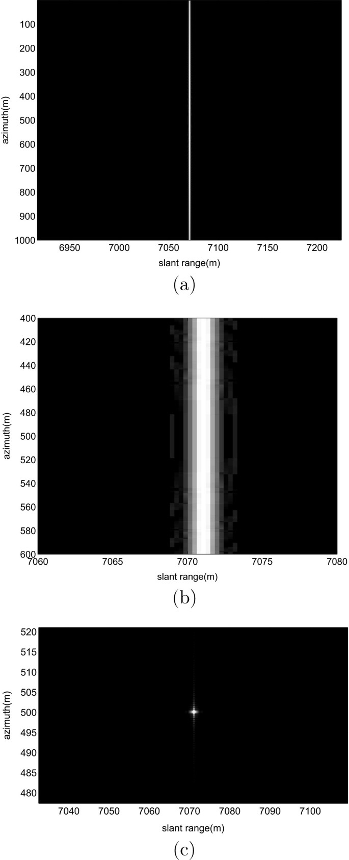
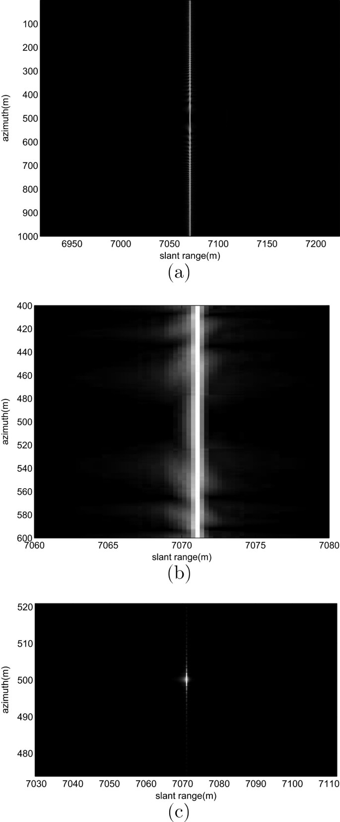
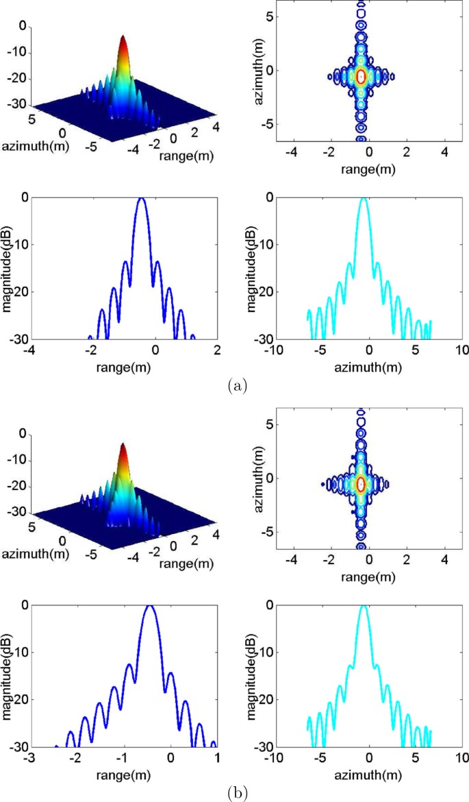
Figure 2 illustrates the increasing process of non-zero points corresponding to different K without interpolation. The bigger K is, the more obvious the sidelobes are. For example, when K = 1, there is only 1 non-zero point, which likes a delta function and when K = 15, there are at least two pairs of sidelobes nearby the peak. Also Fourier interpolation can be carried out for this construction with some sidelobes. Meanwhile, we set K = 11 when we apply the previous CS matrix to the same echoes.To quantitatively analyze the effect of the CS imaging, Figures 3 and 4 show the corresponding results of range reconstruction and final imaging with two kinds of CS matrices.According to the above results, it is easy to find that there are a few sidelobes in both range reconstructions in Figure 3b and Figure 4b. The range reconstruction results based on our proposed method shown in Figure 3 are better than those based on the previous matrix shown in Figure 4. Also, it is easy to find the symmetry of the range result after CS, and the final result by our matrix is better.
Moreover, we evaluate the imaging results with Fourier interpolation, shown in Figure 5. The resolutions and peak sidelobe ratios (PSLR) of both slant range and azimuth profiles are listed in Table 2.
Point quality evaluation results. (a) Results based on our proposed matrix in frequency domain; (b) results based on the previous matrix in time domain. The four subfigures in both (a) and (b) stand the three-dimensional surface, contour image, range profile, and azimuth profile. The two-dimensional and one-dimensional Fourier interpolations are used, and the times of interpolation are 64 and 1,024.
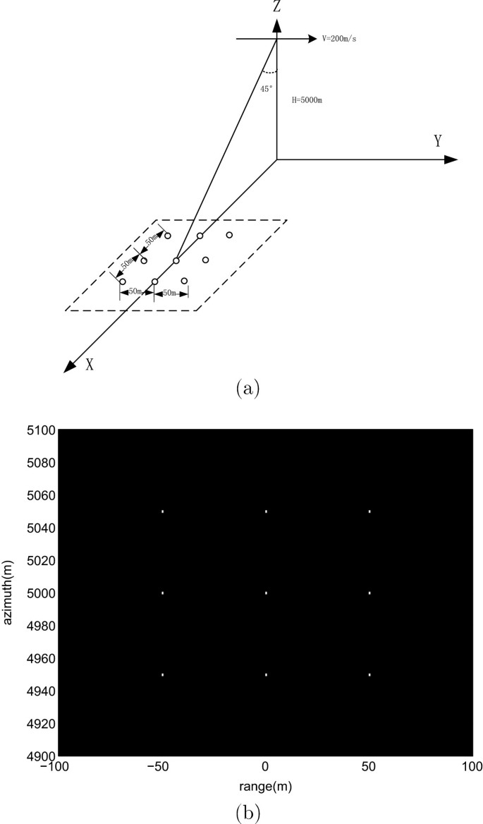
According to Figure 5, the symmetry along with range direction of the result based on our proposed matrix is better than those based on the previous matrix. That is also the main reason of the slant range PSLR difference in Table 2. Also, the evaluation indices of our proposed method are much closer to the theoretical indices. Usually the higher the range resolution is, the better the image effect is. However, the more the indices approach the theoretical values, the better the reconstruction algorithm is. In this respect, the CS imaging based on our proposed matrix is much better.Moreover, a 9-point scene was simulated. Figure 6 displayed the scene and imaging result by our method. Figure 6a shows the 9 points and the imaging geometry. Figure 6b implies that the proposed method based on the CS matrix in the frequency domain is capable of imaging a small set of scatterers.
5 Conclusions
In this paper, the general echo model is derived from Maxwell’s equations. The general echo expressions in both frequency domain and time domain are given after generating the scatter field. The general echo model is the expansion of the classical echo model. Based on the general echo model in the frequency domain, a new CS matrix like a random partial Fourier matrix is constructed to apply for the CS imaging. Simulation results validate the orthogonality of the proposed CS matrix and the indices of the CS imaging by our model approach the theoretical values better. Also a bigger sparse number K will expose the sidelobes of the reconstruction, and Fourier interpolation can be applied into evaluating the imaging results.
References
Soumekh M, Kaveh M: A theoretical study of model approximation errors in diffraction tomography. IEEE Trans. Ultrason. Ferroelectrics Freq. Contr 1986, 33(1):10-20.
Soumekh M: A system model and inversion for synthetic aperture radar imaging. IEEE Trans. Image Process 1992, 1(1):64-76. 10.1109/83.128031
Cheney M: A mathematical tutorial on synthetic aperture radar. SIAM Rev. 2001, 43(2):301-312. 10.1137/S0036144500368859
Nolan CJ, Cheney M: Synthetic aperture inversion. Inverse. Probl. 2002, 18(1):221-235. 10.1088/0266-5611/18/1/315
Lopez JX, Qiao Z: Filtered back projection inversion of turntable ISAR data. Proc. SPIE, vol. 8051 2011, 80510901-80510909. doi:10.1117/12.884419
Fuchs J-J: On the application of the global matched filter to doa estimation with uniform circular arrays. IEEE Trans. Signal Process 2001, 49(4):702-709.
Candès EJ, Romberg J, Tao T: Robust uncertainty principles: exact signal reconstruction from highly incomplete frequency information. IEEE Trans. Inform. Theor. 2006, 52(2):489-509.
Donoho DL: Compressed sensing. IEEE Trans. Inform. Theor 2006, 52(4):1289-1306.
Candes EJ, Tao T: Near-optimal signal recovery from random projections: universal encoding strategies. IEEE Trans.Inform. Theor 2006, 52(12):5406-5425.
Baraniuk R: Compressive sensing. IEEE Signal Process. Mag 2007, 24(4):118-120124.
Baraniuk R, Steeghs P: Compressive radar imaging. In Radar Conference, 2007 IEEE. IEEE; 2007:128-133. doi:10.1109/RADAR.2007.374203
Herman M, Strohmer T: Compressed sensing radar. In Radar Conference, 2008. RADAR’08. IEEE. IEEE; 2008:1-6.
Ender JH: On compressive sensing applied to radar. Signal Process. 2010, 90(5):1402-1414. 10.1016/j.sigpro.2009.11.009
Potter LC, Ertin E, Parker JT, Cetin M: Sparsity and compressed sensing in radar imaging. Proc. IEEE 2010, 98(6):1006-1020.
Lagunas E, Amin MG, Ahmad F, Nájar M: Sparsity-based radar imaging of building structures. In Signal Processing Conference (EUSIPCO), 2012 Proceedings of the 20th European. IEEE; 2012:864-868.
Xu L, Liang Q, Cheng X, Chen D: Compressive sensing in distributed radar sensor networks using pulse compression waveforms. EURASIP J. Wireless Commun. Netw 2013, 2013(1):1-10. 10.1186/1687-1499-2013-1
Xu J, Pi Y, Cao Z: Optimized projection matrix for compressive sensing. EURASIP J. Adv. Signal Process 2010, 2010: 43.
Liang Q: Compressive sensing for synthetic aperture radar in fast-time and slow-time domains. Signals, Systems and Computers (ASILOMAR), 2011 Conference Record of the Forty Fifth Asilomar Conference On 2011, 1479-1483. doi:10.1109/ACSSC.2011.6190264
Zhang L, Xing M, Qiu C-W, Li J, Sheng J, Li Y, Bao Z: Resolution enhancement for inversed synthetic aperture radar imaging under low snr via improved compressive sensing. IEEE Trans. Geosci. Rem. Sens. 2010, 48(10):3824-3838.
Sun B, Qiao Z, Chen J: Outer circular synthetic apeture radar imaging based on maxwell’s equations. J. Appl. Remote Sens 2012, 6(1):06354701-06354711.
Cheney M, Borden B: Fundamentals of Radar Imaging, vol. 79. Siam, California; 2009.
Myint-U T, Debnath L: Linear Partial Differential Equations for Scientists and Engineers. Springer, Birkhäuser Boston; 2007.
Tello Alonso M, López-Dekker P, Mallorquí JJ: A novel strategy for radar imaging based on compressive sensing. IEEE Trans. Geosci. Rem. Sens 2010, 48(12):4285-4295.
Xiao P, Yu Z, Li C: Compressive sensing sar range compression with chirp scaling principle. Sci. China Inform. Sci 2012, 55(10):2292-2300. 10.1007/s11432-012-4613-8
Tropp JA, Gilbert AC: Signal recovery from random measurements via orthogonal matching pursuit. IEEE Trans. Inform. Theor 2007, 53(12):4655-4666.
Xu J, Pi Y: Compressive sensing in radar high resolution range imaging. J. Comput. Inform. Syst 2011, 3: 778-785.
Yang J, Thompson J, Huang X, Jin T, Zhou Z: Segmented reconstruction for compressed sensing sar imaging. IEEE Trans. Geosci. Rem. Sens 2013, 51(7):4214-4225.
Acknowledgements
This work is supported by the National Natural Science Fund of China (Grant Nos. 61301187 and 61328103), and the Fundamental Research Funds for the Central Universities. ZQ thanks the U.S. Department of Education GAANN project (P200A120256) for supporting the UTPA mathematics graduate program. The authors also thank Mr. John Montalbo for his communication and the anonymous reviewers for their valuable suggestions.
Author information
Authors and Affiliations
Corresponding author
Additional information
Competing interests
The authors declare that they have no competing interests.
Authors’ original submitted files for images
Below are the links to the authors’ original submitted files for images.
Rights and permissions
Open Access This article is licensed under a Creative Commons Attribution 4.0 International License, which permits use, sharing, adaptation, distribution and reproduction in any medium or format, as long as you give appropriate credit to the original author(s) and the source, provide a link to the Creative Commons licence, and indicate if changes were made.
The images or other third party material in this article are included in the article’s Creative Commons licence, unless indicated otherwise in a credit line to the material. If material is not included in the article’s Creative Commons licence and your intended use is not permitted by statutory regulation or exceeds the permitted use, you will need to obtain permission directly from the copyright holder.
To view a copy of this licence, visit https://creativecommons.org/licenses/by/4.0/.
About this article
Cite this article
Sun, B., Cao, Y., Chen, J. et al. Compressive sensing imaging for general synthetic aperture radar echo model based on Maxwell’s equations. EURASIP J. Adv. Signal Process. 2014, 153 (2014). https://doi.org/10.1186/1687-6180-2014-153
Received:
Accepted:
Published:
DOI: https://doi.org/10.1186/1687-6180-2014-153
